 Rescue systems Stratos 07 s.r.o.


Installation and function of rescue systems
For more information please download our entire manual here: MANUAL
Installation location for the MAGNUM rescue system and shot direction
It is not recommended to aim the system below the aircraft because it will allow for a large altitude loss and it will take longer for the aircraft to stabilize.
If the system is aimed vertically and activated during horizontal flight, it may be possible for the aircraft to swing up above the level of the canopy. There will be an excessive loss of altitude and the plane will swing excessively, taking longer to stabilize.
It has been verified through tests during horizontal flight, that by firing the parachute off to the side, minimum altitude is lost. Because most documented activations have been in a similar flight attitude, it can be assumed that the optimal position would be to aim the rescue system to the side, and up from 0° to 45°. It is important to consider the position of the aircraft stabilization rudder and the elevator.

When the system is aimed to the side, the canopy will begin to fill and pull the plane into a gentle circle and stabilize it very quickly. The altitude loss is less than by aiming vertically upward.
Influence of changes in center of gravity on the rescue system mounting
 It is important to consider the weight of the rescue system and the impact of its placement on the location of the center of gravity of the airplane!
Where not to mount the rescue system
It is not allowed to mount the rescue system on aircraft parts which strongly vibrate (landing gear, motor mount, etc.) or near fuel tanks or fuel lines; a fireproof bulkhead may be the solution. The rocket motor must be positioned so as not to threaten the crew! The suspension cables must be routed in such a way so that when tightened during parachute activation, they do not injure the crew!
The aircraft suspension points must be in a stable configuration so that the landing gear contacts the ground first; this requires at least 3, preferably 4 anchorage points. For low wing aircraft, it is recommended to adjust the suspension such that the wing tip makes first contact with the earth and then gradually the landing gear. This rolling considerably reduces the landing impact.
The configuration of the ejection for internally mounted aircraft rescue systems
The location of the cover must be such that the deployment of the rescue system is not compromised.
The edges of the opening for the rescue system nor any other component must not be sharp! Sharp edges will damage the rescue system. The rocket and softpack axis must be perpendicular to the exit surface.
Location of the Magnum rescue system activation handle
- The handle must be within the reach of both pilots.
- There must be two activation handles in cases where the two pilots are sitting in a row behind each other.
- The activation handle must be located so that both pilots see it during the flight with their peripheral vision! This location helps quicken the reaction time to activate the rescue system!
- Do not install the activation handle out of your visual field or in an inaccessible area such as behind your head, on the floor, etc. During an accident, the centrifugal forces may be so high that it would not be possible to reach the handle.
From a physiological point of view, one has the most strength with bent arms around one’s lap in the seated position. With the pilots sitting side-by-side, the best location for the handle would be on the instrument panel between both pilots. The handle must be within reach of the hand from a seated position with the neck and back firmly placed against the seat.
Aircraft types and rescue system location


Aktivation of the rescue system

After the activation handle is pulled, the movement is mechanically transposed by cable to an ignition device, which activates two igniters in the rocket combustion chamber. Through combustion, gases expand, and escape under high pressure from the combustion chamber through a nozzle which propels the rocket out of the aircraft. The rocket deflects specially designed aircraft cover. The rocket has a sharp tip enabling it to break through a specially designed softer cover materials. As the rocket is propelled, it pulls a cable which opens the parachute container. The parachute hidden in the parachute sleeve is briskly pulled out and away of the aircraft with its connecting chord by the rocket. The parachute sleeve slides back from the canopy in the direction of the apex vent, ensuring the canopy is smoothly and symmetrically loaded at low or high speeds.
This design prevents the canopy from an uncontrolled fill which would damage the canopy. Additionally, the design eliminates potential damage while being extracted out of the aircraft, reduces excessive forces incurred during deployment, and it restricts asymmetric filling of the canopy.
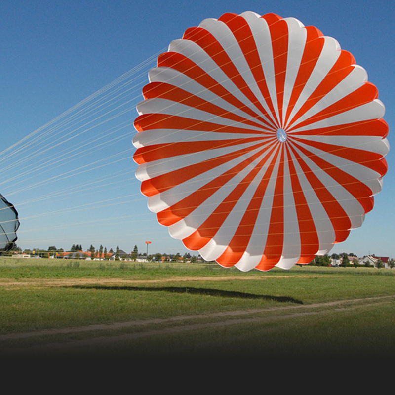
The parachute of the MAGNUM rescue systems are designed to fully open in the shortest possible time, but with increased damping during the canopy deployment. Some types of parachute have a slider to help reduce possible overloading.
Minimum effective altitude for the use of the MAGNUM rescue systems
It is generally recommended to activate the rescue system at heights greater than 200m above ground! Even at lesser heights, the MAGNUM rescue system may save your life.
Nonetheless, it is necessary to be aware that the success of low altitude recovery will always depend on your horizontal and vertical speeds at the moment of activation.
Our rescue systems are also tested at a speed of 100 km/h. In these tests the minimum safe deployment altitude during horizontal flight is measured. This altitude shows our tables of all RS.
Referring to numerous years of experience, it is key to note that the MAGNUM rescue system may work even at very low altitudes and save human lives. In emergencies, it is recommended to activate the MAGNUM rescue system even at altitudes which are below limits; even this option offers a considerable chance of rescue!